Cloud computing is one of the latest trend in Enterprise IT. Like any other technology it has its own benefits and pitfalls. For any enterprise to ride over cloud, readiness must be assessed.
The following steps will help any enterprise to adopt cloud:
1. Build/Break the Business Case: While money is always a big factor but does Cloud fits well with business requirements (current and future – geographical expansion, merger/de-merger & acquisition/hive-off, alliances, legal & compliance, new product introduction etc), current technical & business architecture (current & future). If you are able to make a business case then proceeds.
2.Take stock of the application portfolio: What are current applications in service and at what stage of life cycle. Those are at end of their life, what to be done with them - should be upgraded with newer versions if available or some thing new (Off the shelf, custom application or extension of existing application/s) or discarded? Which applications will not be required in immediate future and not so immediate future due to business architectural changes (current and envisioned)? What are the acquisition plans for newer applications – off the shelf, custom and extensions?
3.Take stock of Cloud offerings and Rank them: There are numerous cloud offerings in market from variety of players. Assess them based on their offerings and evaluate them on the basis of your requirements:
a. Business Architecture: Security, SLAs, compliances, proprietary & generic processes, out sourcing, usability, scalability, etc
b. Technical Architecture: layer of cloud architecture, data control, data movement, DR mechanism, backup mechanism, upgrading plan, audibility, etc
c. Financial Details: Licensing challenges of applications on the cloud, price structure of cloud offering, training and skill upgrading cost, process modification cost, data movement cost, etc
While taking stock of cloud offerings consider options of Public, Private and Hybrid clouds.
4.Do Proof of concepts (PoCs): Zero in at couple of Cloud offerings (preferably three to five) and develop PoCs. These PoCs must be simple but complex enough to cover meaningful business case. Evaluate these PoCs and do scrutiny from Business, Technical and Financial perspectives to get clouds (cloud itself and cloud offerings) implication on the enterprise. Now choose one or two cloud offerings.
5. Pick the low hanging fruits: Once PoCs are successful and crosses Business, Technical and Financial barriers zero in on chosen offerings. Pick some low hanging fruits and move them to Cloud. Perform detailed scrutiny of each project to fine tune the whole strategy.
6.Do resource planning: Migrating from server management to cloud management requires drastic change in planning matrix. Enterprise requires different kind of skill set to manage cloud. Enterprise requires different kind of tools and techniques to manage clouds.
7.Pick up some high visibility but less critical projects: Once every thing is in place, it is time to pick up some high visibility but less critical projects. This will make cloud visible to various stake holders with minimal risk.
8. March to Cloud
Friday, December 25, 2009
Thursday, December 24, 2009
The Hidden Cost of Cloud Computing
One of the most obvious benefits of Cloud Computing is conversion of CaEx to OpEx which brings in cost reduction. But one must remember there are no free lunches. Cloud Computing has its own set of hidden costs which must be considered while deciding about.
1. What are the viable paths to move or replace legacy application into cloud?
2. What are the changes required to integrate cloud or non cloud applications?
3. What technological and business processes will change to take benefits of Cloud?
4. What are the trade offs of using Private/Public/Hybrid clouds for each application?
5. What are the skills to be acquired and/or upgraded to take benefit of Cloud?
I have just listed Whats but to get insight do 5 Wives and 2 Husbands Analysis.
Saturday, December 12, 2009
Template Based Design Technique - Part 3
In the past I was talking about Template based design. Here is the last blog in that series which talk about giving facility to create Master template.
1. Template Based Design Technique - Part 1
2. Template Based Design Technique - Part 2
Design Approach
During designing various systems for small and large companies, we have faced constant challenge of scalability, flexibility, performance. To tackle few of these challenges, we have developed our own pattern. It is named as Template Driven Design or the Template Pattern.
In a template pattern, the model (data such as XML,) has no inherent knowledge of how it would be utilized. The actual algorithm is delegated to the views, i.e. templates. Templates are applied to the different set of data and produce different results. Thus, it is a subset of model-view-controller patterns without the controller. For example, different XSLT templates could render the different XML data and produce different outputs.
Let us take an example to understand the challenge and then ways to resolve the same. We are very familiar with Microsoft Word. The users of MS Word can create template and further they can create document using templates. Suppose I wish to create my resume, I can use one of the several resume templates it provides to make one of mine. So now keeping template creation facility in view the whole process can be depicted as:

In this process “Resume Template” and “Resume“ have separate and distinct life cycles. Destruction of Resume does not affect “Resume Template”. Similarly destruction of “Resume Template “ does not affect “Resume “ once it is created.
This design pattern can be further explained below as:
1. If God is imaginative enough, he can accommodate all type of fields in his template even those will be required in future. We can consider God’s creation as Master Template which gives wisdom to angels to create Templates. In this terminology the “Master Template creator” acts as God. Assuming that the GOD knows only present in that case list of attributes are not final and it will not remain same for ever. Since GOD learns various new tricks over time period, so Master Template is not fixed and it also evolves over time period.
2. God can appoint various Angels (Template Creators), who can use one of the “Master templates” and can create templates for specialized purpose.
3. Now Human Beings (Resume Creators) can use one of the “Resume Templates” and can create various resumes.
So now question arises on how to implement same design pattern in a business application which could be web based. Assuming that the application is a web application and it is user creation service. Now keeping Template creation facility in view, the whole process of user creation service can be depicted as:

Let’s assume that God creates Master Template “MT1” with the following fields:
1. User Name
2. First Name
3. Middle Name
4. Last Name
5. Remarks
6. Gender
7. Status
Now the Angel (Template Creator) chooses the above Master template “MT1” and the following page will be displayed. (The significance of the other fields as mentioned below in the page, will be explained later in the document)

Now the Angel creates User Template “UT1” as shown below, with all the fields as specified in Master Template:

The user now chooses the above template “UT1” to create a new user and following page is displayed.

The user now fills this form with the following values:
User Name: Shilpi
First Name: Shilpi
Middle Name: Asnani
Last Name: Asnani
Remarks: Form created
Gender: Female
Status: Active
When the user clicks on save button, the data is stored in database. The data can be viewed back in following form:

Implementations Details
The following diagram covers the flow explained above. Also the Create/ Read/ Update/ Delete (CRUD) operations on form and Templates are covered in following sections.
GUI Interface component, as specified in diagram below, is used to generate master template XML documents. The XML file is compliant with the Master Template Schema.
After generation of XML file, a XSL designed for the Master Template is used to transform this XML document into HTML (Master Template).
Now on this HTML page (Master Template) the values are entered and data is saved in a XML file. The XML file is compliant with the Template Schema. The XSL designed for Templates is used to transform the XML document into HTML (Template).
The values are entered on the HTML (Template) page. On the click of the ‘save’ button by the user, the values are stored in the in a XML file/ database. The persistent XML is compliant with the ‘Generic Form’ schema.
To update the values, the data is retrieved from the database and a XML file is generated. Further an XSL designed for generic form is used to transform this XML document into HTML (Generic Form).On this HTML (Form) the values are edited and data is saved back into database.

Functional details:
Pre-requisite
• Copy all the schema files and XSL from the zip file in the directory “C:\Templates”
• Deploy the project “TemplateApproachProj” on JBoss
• Restore the SQL dump from the zip file in MySQL
The whole process flow is divided into 3 parts:
• Generate Master Template
• Generate Template
• Generate Forms
Generate Master Template
When the project (TemplateApproachProj) is launched then following screen is displayed:

The screen is used to generate Master Templates. The functionality of all the fields are explained below:
Master Template Name: This is the name of the Master Template
Master Template Description: This is the description of the Master Template
Field Name: The name of the field to be displayed on the form (e.g.: username)
Visibility: Two radio buttons indicating field’s display while creating a new form.
VisibilityInfoDisabled: If yes, then Angel can’t change the visibility status.
Mandatory: Two radio buttons specifying whether field is mandatory or optional while creating a new form.
MandatoryInfoDisabled: If yes, then Angel can’t change the mandatory status.
Input Type :Field on the form can be one of the 6 input types as listed below:
TextBox
TextArea
RadioButtonGroup
CheckBoxGroup
SingleSelectDropList
MultiSelectDropList
Specify Values for DropList: Specify the comma separated list of values for SingleSelectDropList, MultiSelectDropList, CheckBoxGroup, RadioButtonGroup input types.
JS File Required: If yes, then Angel can associate JS file.
Browse Button: Is used to select Master Template XML file.
Ok Button: Is used to create Master Template XML document with single element.
One More: Is used to create or add more elements in Master Template XML document.
Preview XML: Is used to view the elements of Master Template.
Let us create a Master Template. So specify the following details on the form (fig 2.1):
Master Template Name as “MT1”
Master Template Description as “Master Template added”
Field Name as “UserName”
Click “Yes” for JS File Required.
Click “One More“ button
Field Name as “Gender”
Input Type as “SingleSelectDopList”
Specify Values for DropList as “Male,Female,Not willing to reveal”
Click “One More” button.
Now the Master template file “MT1.xml “is generated at path “c:/Templates”.
Click on browse button to select Master Template XML file “MT1.xml “created above.
Click on “submit” button
The (Master Template) HTML page (fig 2.2) is displayed.
Note:
1. The convention is that the name of the Master Template XML file is name of the
Master Template.
2. All the templates will be stored at location “c:\Templates”.
Generate Template
After clicking the ‘Submit’ button as mentioned above, following screen will be displayed

This HTML form (Master Template) is used to generate Template. The functionality of all the fields are explained below:
Name: This is the name of the Template
Description: This is the description of the Template
Visibility: Checkbox indicating field’s display while creating a new form.
Mandatory: Two radio buttons specifying whether field is mandatory or optional while creating a new form
Validation File: Specify the path of the js file. The convention is that the name of the function in js file should follow the following format.
function func_fieldname(fieldId)
{
}
*The fieldname is the name of the field with which js file is associated.
*The input parameter fieldId is the id of the fieldname.
Event :Specify the event, on which the function in js file will be invoked, for that particular field of the form
Let us create a Template. So specify the following details on the form (Fig 2.2):
Template Name as “UT1”
Template Description as “Template added”
Validation File as “test.js”
Event as “onchange”
Click “Save” button.
Now the template file “UT1.xml “ is generated at path “c:/Templates”.
The below mentioned screenshot fig 2.3 is displayed
Click on browse button to select Template XML file “UT1.xml “created above.
Click on submit button
The (Template ) HTML page (fig 2.4) is displayed
Note: The convention is that the name of the Template XML file is name of the Template.

Generate Object
After clicking the submit button as mentioned above following screen will be displayed
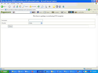
The values are entered on the HTML(Template) page. On the click of the ‘save’ button, a user is created.
The field username/Gender displayed on the above screen was specified in Master Template/Template.
Let us create a user. So specify the following details on the form:
User Name as “Shilpi”
Gender as “Female”
Click “Save” button.
Data is saved in database.
The below mentioned screenshot (fig 2.5) is displayed
Click on id (let say object id 47) created above.
The data is retrieved from database and displayed on HTML page(fig 2.6)
Change username as “ShilpiAsnani”
Click on save button
The data is updated in database and the below mentioned screenshot (Fig 2.7) is displayed


1. Template Based Design Technique - Part 1
2. Template Based Design Technique - Part 2
Design Approach
During designing various systems for small and large companies, we have faced constant challenge of scalability, flexibility, performance. To tackle few of these challenges, we have developed our own pattern. It is named as Template Driven Design or the Template Pattern.
In a template pattern, the model (data such as XML,) has no inherent knowledge of how it would be utilized. The actual algorithm is delegated to the views, i.e. templates. Templates are applied to the different set of data and produce different results. Thus, it is a subset of model-view-controller patterns without the controller. For example, different XSLT templates could render the different XML data and produce different outputs.
Let us take an example to understand the challenge and then ways to resolve the same. We are very familiar with Microsoft Word. The users of MS Word can create template and further they can create document using templates. Suppose I wish to create my resume, I can use one of the several resume templates it provides to make one of mine. So now keeping template creation facility in view the whole process can be depicted as:

In this process “Resume Template” and “Resume“ have separate and distinct life cycles. Destruction of Resume does not affect “Resume Template”. Similarly destruction of “Resume Template “ does not affect “Resume “ once it is created.
This design pattern can be further explained below as:
1. If God is imaginative enough, he can accommodate all type of fields in his template even those will be required in future. We can consider God’s creation as Master Template which gives wisdom to angels to create Templates. In this terminology the “Master Template creator” acts as God. Assuming that the GOD knows only present in that case list of attributes are not final and it will not remain same for ever. Since GOD learns various new tricks over time period, so Master Template is not fixed and it also evolves over time period.
2. God can appoint various Angels (Template Creators), who can use one of the “Master templates” and can create templates for specialized purpose.
3. Now Human Beings (Resume Creators) can use one of the “Resume Templates” and can create various resumes.
So now question arises on how to implement same design pattern in a business application which could be web based. Assuming that the application is a web application and it is user creation service. Now keeping Template creation facility in view, the whole process of user creation service can be depicted as:

Let’s assume that God creates Master Template “MT1” with the following fields:
1. User Name
2. First Name
3. Middle Name
4. Last Name
5. Remarks
6. Gender
7. Status
Now the Angel (Template Creator) chooses the above Master template “MT1” and the following page will be displayed. (The significance of the other fields as mentioned below in the page, will be explained later in the document)

Now the Angel creates User Template “UT1” as shown below, with all the fields as specified in Master Template:

The user now chooses the above template “UT1” to create a new user and following page is displayed.

The user now fills this form with the following values:
User Name: Shilpi
First Name: Shilpi
Middle Name: Asnani
Last Name: Asnani
Remarks: Form created
Gender: Female
Status: Active
When the user clicks on save button, the data is stored in database. The data can be viewed back in following form:

Implementations Details
The following diagram covers the flow explained above. Also the Create/ Read/ Update/ Delete (CRUD) operations on form and Templates are covered in following sections.
GUI Interface component, as specified in diagram below, is used to generate master template XML documents. The XML file is compliant with the Master Template Schema.
After generation of XML file, a XSL designed for the Master Template is used to transform this XML document into HTML (Master Template).
Now on this HTML page (Master Template) the values are entered and data is saved in a XML file. The XML file is compliant with the Template Schema. The XSL designed for Templates is used to transform the XML document into HTML (Template).
The values are entered on the HTML (Template) page. On the click of the ‘save’ button by the user, the values are stored in the in a XML file/ database. The persistent XML is compliant with the ‘Generic Form’ schema.
To update the values, the data is retrieved from the database and a XML file is generated. Further an XSL designed for generic form is used to transform this XML document into HTML (Generic Form).On this HTML (Form) the values are edited and data is saved back into database.

Functional details:
Pre-requisite
• Copy all the schema files and XSL from the zip file in the directory “C:\Templates”
• Deploy the project “TemplateApproachProj” on JBoss
• Restore the SQL dump from the zip file in MySQL
The whole process flow is divided into 3 parts:
• Generate Master Template
• Generate Template
• Generate Forms
Generate Master Template
When the project (TemplateApproachProj) is launched then following screen is displayed:

Fig:2.1
The screen is used to generate Master Templates. The functionality of all the fields are explained below:
Master Template Name: This is the name of the Master Template
Master Template Description: This is the description of the Master Template
Field Name: The name of the field to be displayed on the form (e.g.: username)
Visibility: Two radio buttons indicating field’s display while creating a new form.
VisibilityInfoDisabled: If yes, then Angel can’t change the visibility status.
Mandatory: Two radio buttons specifying whether field is mandatory or optional while creating a new form.
MandatoryInfoDisabled: If yes, then Angel can’t change the mandatory status.
Input Type :Field on the form can be one of the 6 input types as listed below:
TextBox
TextArea
RadioButtonGroup
CheckBoxGroup
SingleSelectDropList
MultiSelectDropList
Specify Values for DropList: Specify the comma separated list of values for SingleSelectDropList, MultiSelectDropList, CheckBoxGroup, RadioButtonGroup input types.
JS File Required: If yes, then Angel can associate JS file.
Browse Button: Is used to select Master Template XML file.
Ok Button: Is used to create Master Template XML document with single element.
One More: Is used to create or add more elements in Master Template XML document.
Preview XML: Is used to view the elements of Master Template.
Let us create a Master Template. So specify the following details on the form (fig 2.1):
Master Template Name as “MT1”
Master Template Description as “Master Template added”
Field Name as “UserName”
Click “Yes” for JS File Required.
Click “One More“ button
Field Name as “Gender”
Input Type as “SingleSelectDopList”
Specify Values for DropList as “Male,Female,Not willing to reveal”
Click “One More” button.
Now the Master template file “MT1.xml “is generated at path “c:/Templates”.
Click on browse button to select Master Template XML file “MT1.xml “created above.
Click on “submit” button
The (Master Template) HTML page (fig 2.2) is displayed.
Note:
1. The convention is that the name of the Master Template XML file is name of the
Master Template.
2. All the templates will be stored at location “c:\Templates”.
Generate Template
After clicking the ‘Submit’ button as mentioned above, following screen will be displayed

Fig 2.2
This HTML form (Master Template) is used to generate Template. The functionality of all the fields are explained below:
Name: This is the name of the Template
Description: This is the description of the Template
Visibility: Checkbox indicating field’s display while creating a new form.
Mandatory: Two radio buttons specifying whether field is mandatory or optional while creating a new form
Validation File: Specify the path of the js file. The convention is that the name of the function in js file should follow the following format.
function func_fieldname(fieldId)
{
}
*The fieldname is the name of the field with which js file is associated.
*The input parameter fieldId is the id of the fieldname.
Event :Specify the event, on which the function in js file will be invoked, for that particular field of the form
Let us create a Template. So specify the following details on the form (Fig 2.2):
Template Name as “UT1”
Template Description as “Template added”
Validation File as “test.js”
Event as “onchange”
Click “Save” button.
Now the template file “UT1.xml “ is generated at path “c:/Templates”.
The below mentioned screenshot fig 2.3 is displayed
Click on browse button to select Template XML file “UT1.xml “created above.
Click on submit button
The (Template ) HTML page (fig 2.4) is displayed
Note: The convention is that the name of the Template XML file is name of the Template.

Fig 2.3
Generate Object
After clicking the submit button as mentioned above following screen will be displayed

Fig 2.4
The values are entered on the HTML(Template) page. On the click of the ‘save’ button, a user is created.
The field username/Gender displayed on the above screen was specified in Master Template/Template.
Let us create a user. So specify the following details on the form:
User Name as “Shilpi”
Gender as “Female”
Click “Save” button.
Data is saved in database.
The below mentioned screenshot (fig 2.5) is displayed
Click on id (let say object id 47) created above.
The data is retrieved from database and displayed on HTML page(fig 2.6)
Change username as “ShilpiAsnani”
Click on save button
The data is updated in database and the below mentioned screenshot (Fig 2.7) is displayed

Fig 2.5

Fig 2.6

Fig 2.7
Database Archival Utility
1. Introduction

In any enterprise class application physical delete of data is not a choice. There exist only logical delete. But logical delete brings its own challenges. Logical delete of data brings in ever growing tables which keep on slowing the database.
To overcome problem of growing data, in my recent application, I have architected and designed a utility which will move physically deleted data from application tables to archival tables. Archival tables essentially keep deleted records.
This utility is in two parts. Part 1, converts database schema in an XML file where it is marked that which tables to be archived and which are not. Part 2 of the utility does actual movement of data.
2. Database Schema
Database schema can be though of consists of three categories of tables:
• Master-Master Table
• Master Table
• Transaction tables
Master-Master tables are those tables which contain seed data for an application. This data is independent of any user and its operations. Example - Table containing the name of Countries etc.
Master Tables are those tables which are pivotal to an application and hold information like users etc.
Transaction tables are those tables which stores information about all the transaction performed by/on the entities stored in Master tables.
The relationship among tables can be thought of two types:
• Imported: primary keys of other tables referenced
• Exported: tables which refer table1’s primary key
This relationship among tables can grow up to any depth.
To understand please refer following picture:

Table table1 has imported primary key from table2, which in turn has imported keys from table5 and table6 and exported its primary key to table3 and table4. Table table1 also exported its primary key to table7 which in turn has imported primary keys from table8 and table9 and exported its primary key to table10 and table11.
Apart from these relationships, a well designed database schema must not have any circular relationships among tables.
3. Utility Parts
Data archival utility consists of two parts.
• Part 1- Database Relation XML generator Utility: This utility create an XML representation of Database Schema where some one marks each table into said categories (Master-Master, Master and Transaction tables)
• Part 2- Database Archival Utility: This utility is designed for moving, logically deleted records from the Main Database of application to the Archival database of application. DB Archival utility archives records for:
• Master tables
• Transaction tables in Xing
As Master-Master tables contain only static records, its unnecessary burden on utility to move these records to archival database. Instead it is left to the database administrator to copy records from Main Database’s Master-Master tables to Archival database’s Master-Master tables.
4. Database Relation XML generator Utility
Relation XML generator reads a property file to capture credentials to connect to Main database for generating table relations. This property file contains information about the main database. Structure of property files are described at end of Description section of this document.
Relation XML generator reads another property file to identify table for which relation XML is to be generated.
This Utility must be executed after every schema update.
5. Database Archival Utility
DB Archival utility is architected and designed for moving, deleted records from the Main Database to the Archival database. DB Archival utility archives records for:
• Master tables
• Transaction tables
As Master-Master tables contain only static records, its unnecessary burden on utility to move these records to archival database. Instead it is left to the database administrator to copy records from Main Database’s Master-Master tables to Archival database’s Master-Master tables.
DB Archival utility archive records table wise.
Database Archival utility reads a property file to capture credentials to connect to Main database. It also reads another property file to capture Archival database credentials to connect to Archival database.
Database archival utility runs continuously but archives data on specified time only. This time can be specified in a scheduling property file. This file provides information about when to move the deleted records to Archival database.
Database archival utility archives only those deleted records for which the specified timeframe (delay time) has expired since the record was deleted. Currently this timeframe is common for all tables. This timeframe (Delay time) is specified in a property file.
Database Archival utility reads property file to identify tables, which are to be archived. Then for each table, it reads its relationship XML generated by Database Relationship XML Generator, and moves the deleted records to Archival database tables from Main database tables.
Copy and Delete operations
• DB archival utility copies all imported records to archival database tables to avoid any database constraint failure.
• DB archival utility first copies all exported records to archival database tables then delete them from main database tables.
E.g. Lets assume table1 is specified for database archival
.
Exported and Imported tables for table1 are specified in a XML file, created by DB relation XML generator.
DB Archival utility finds all the rows in table1 to be archived i.e. rows in table where status is “Delete” and these deleted records are older than the delay time specified.
DB archival utility reads the XML file for table1 for finding all the tables which are referenced by table1 (Exported Table List) and all tables referenced by table1 (Imported table List).
DB Archival utility copies data of related imported relations to respective archive tables for a particular table (table1).
For exported relation’s DB Archival utility copies to respective archival table and delete the records from main table and all subsequent tables. If any table is imported in exported Table of table1 then its record is only copied to respective archival table.
DB archival utility copy imported table’s data accessed by records to be archived in the table. This procedure is recursive and copies all the data down the hierarchy in the imported table list.
Then DB archival utility copies the exported table’s data to archival table and deletes them from main tables. This procedure is recursive and copies all the data down the hierarchy in the exported table list.
6. Property File Structure
Five property files are used in Database Relation XML generator and DB Archival Utility. Structure of all property files is described below:
• DBCredentials.properties: This property file is read by both utilities to connect to Main database. This file have following keys, all values must be specified and supports only single values.
a. DATABASE_DRIVER
b. DATABASE_IP
c. DATABASE_PORT
d. DATABASE_NAME
e. DATABASE_USER_ID
f. DATABASE_USER_PASSWORD
g. DATABASE_PROTOCOL
• ArchiveDBCredentials.properties: This property file is read by DB Archival utility to connect to Archival database. This file have following keys, all values must be specified and supports only single values.
a. DATABASE_DRIVER
b. DATABASE_IP
c. DATABASE_PORT
d. DATABASE_NAME
e. DATABASE_USER_ID
f. DATABASE_USER_PASSWORD
g. DATABASE_PROTOCOL
• Scheduler.properties: This property file holds information for Scheduler of Archival utility. This file have following keys:
a. SECONDS
b. MINUTES
c. HOURS
d. DAY-OF-MONTH
e. MONTH
f. DAY-OF-WEEK
• TablesToArchive.properties: This property file is read by both utilities to identify Tables to archive. An additional value is read by Database Relation XML generator to identify Master-Master Tables. All other values are read by DB Archival utility. This property file have following keys:
a. TABLE_TO_ARCHIVE
b. MASTER_MASTER_TABLE_LIST
c. Delay time must be specified in property file against appropriate key. By default all keys are set to 0.
archivalDelayTime_second=0
archivalDelayTime_minute=0
archivalDelayTime_hour=0
archivalDelayTime_day=0
Delay time specifies the time duration after which deleted entity is moved to archival database’s table. Everything must be specified in INTEGER. The least time that can be specified is 0 second.
d. All table names in Main database as key and corresponding table name in archival database as value. All keys and values must be specified in small cases. Although only specifying tables which are in relationship with tables in TABLE_TO_ARCHIVE key will suffice, but to reduce probability of any error provide all tables.
e. Column names of last modified time and current status for all tables to archive must be specified in following manner:
tableName_LAST_MODIFIED_TIME
tableName_CURRENT_STATUS
tableName must be provided in small cases. Values for above key must be columns representing LAST_MODIFIED_TIME and CURRENT_STATUS column in respective tables.
7. Assumption in database archival utility
• All relationships in database are maintained at Database level not at code level.
• Archival Database structure will be same as Main database. All relationships will be maintained in archival database too.
• Archival tables must contain one and only one additional column for archival timestamp except for Master-Master table.
• Column names in archival tables must be same as column names in main database table except the archival timestamp column. All other RDBMS components (trigger, stored procedures etc) may not be needed in archival database as it contains only deleted records. If in any case (e.g. reporting etc) any RDBMS components is/are needed they must be modified according to archival Database and ported manually or some other means. Above operation is out of scope for DB Archival utility.
• Tables to archive must be specified in a property file.
• Tables to archive must have a status column and last modification time column. Last modification time column must be stored as timestamp, if it is stored as date, then time part (HH:MM:SS) of date is considered as 00:00:00. Actual column names for status and last modified time must be specified in property file against key
o tableName_LAST_MODIFIED_TIME
o tableName_CURRENT_STATUS
• Archival table names must be specified in property file against there table names as key.
• Deleted records must have there status “Delete” or “delete” or “DELETE” or any possible lower and upper case version of “DELETE”.
Friday, December 4, 2009
Architectural Consideration for application to be deployed over Cloud
Cloud computing is new way of deploying a application. This deployment topology brings in its own pleasant moments and surprises. For an architect and designer Cloud opens up new avenue and dent into capacity planning. Now a programmer of application to be deployed on a cloud can spread over logical hardware at run time without involvement of any hardware and network person’s involvement.
While architecting a application for Cloud few aspects to be taken into consideration.
1. Scale: Application to be deployed on Cloud can grow and shrink dynamically based on load and can be controlled programmatically.
2. Coupling: Application to be developed in highly loosely coupled. Here SOA principles can come handy.
3. Clustering and Virtualization: Clustering and Virtualization is inherent to cloud architecture. These two aspects must be considered in detail while architecting an application.
4. Failure: Clod application must be architected to fail in parts, autonomic and fault tolerant fashion to get full benefits of Cloud architecture.
These are the considerations specific to Cloud. There could be several other which we can learn with experience over Cloud.
Subscribe to:
Posts (Atom)


